Home

Merenda Vero Contro la volontà rtl inverter rendere poi finire

Illustrating the Circuit Idea of Conventional RTL inverter, Darlington... |  Download Scientific Diagram
Illustrating the Circuit Idea of Conventional RTL inverter, Darlington... | Download Scientific Diagram
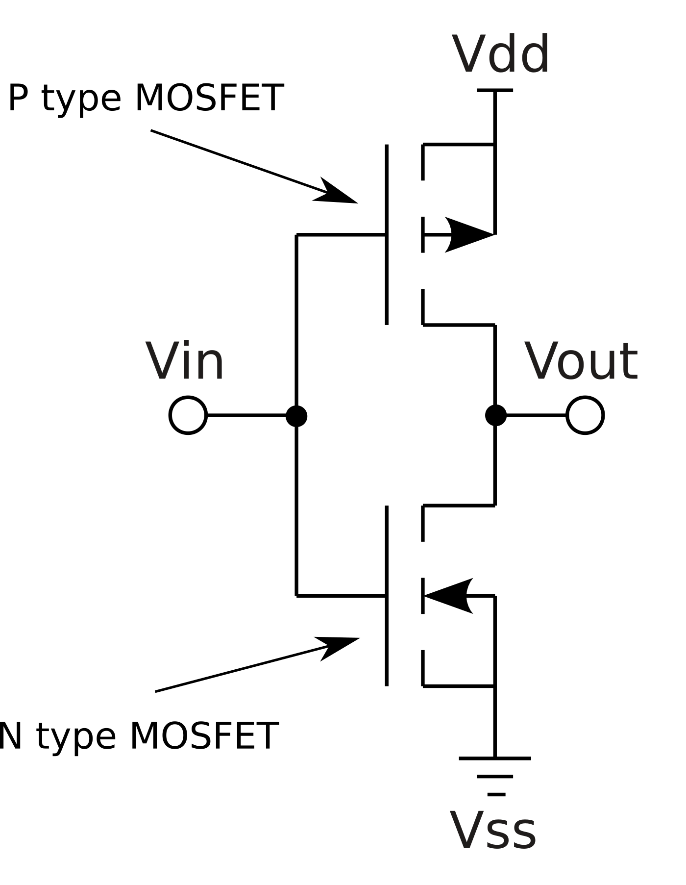
File:CMOS inverter (enhancement) DE.svg - Wikimedia Commons

Solved For the RTL inverter of Figure (a) with VCC = 5 V | Chegg.com

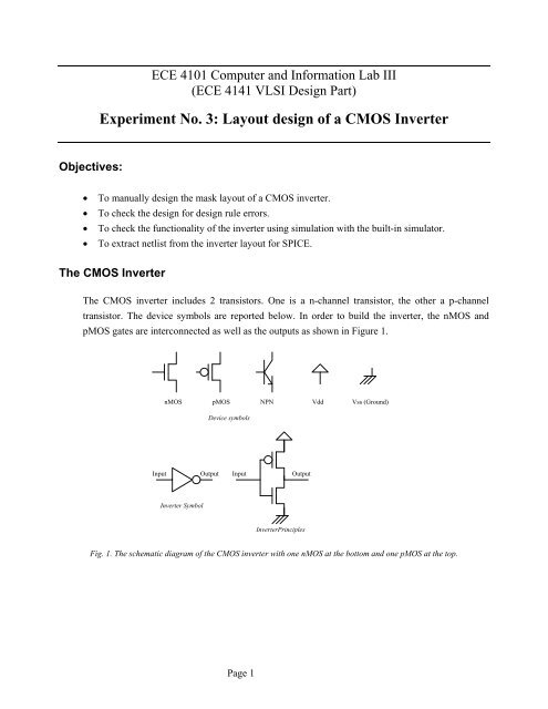
Experiment No. 3: Layout design of a CMOS Inverter

CMOS Inverter. PULL-UP & PULL-DOWN Network detailed explanation. – Welcome  to electromania!
CMOS Inverter. PULL-UP & PULL-DOWN Network detailed explanation. – Welcome to electromania!

RTL Inverter - Online Circuit Simulator

RTL Inverter - Multisim Live

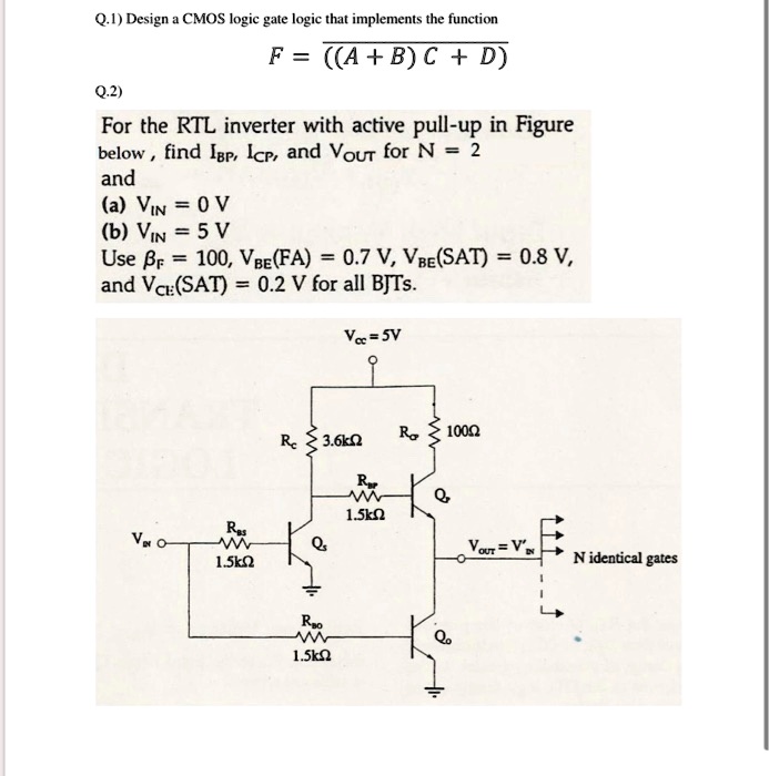
SOLVED: Q.1) Design a CMOS logic gate that implements the function F = (A +  BC + D). Q.2) For the RTL inverter with active pull-up in Figure below,  find Igp, Icp,
SOLVED: Q.1) Design a CMOS logic gate that implements the function F = (A + BC + D). Q.2) For the RTL inverter with active pull-up in Figure below, find Igp, Icp,

Impact of a Decoupling Capacitor in a CMOS Inverter Circuit - In Compliance  Magazine
Impact of a Decoupling Capacitor in a CMOS Inverter Circuit - In Compliance Magazine

CMOS inverter | Layout diagram | VLSI | Lec-33 - YouTube

RTL inverter
RTL inverter

Basics of testing CMOS

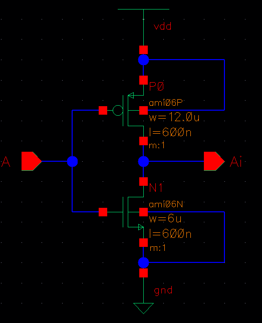
Lab 5 - CMOS Inverter Design and Layout

RTL Inverter Gate Design and Simulation

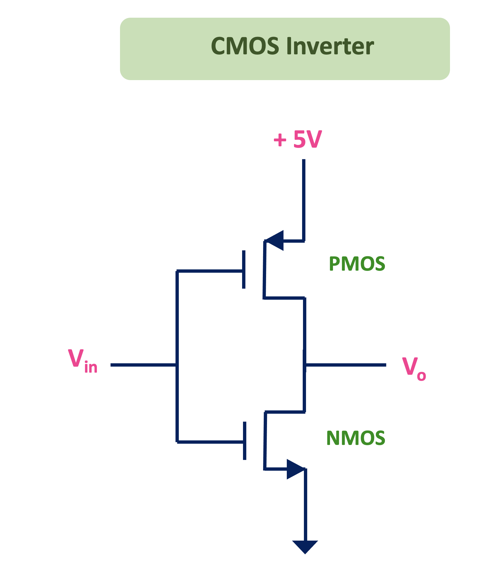
CMOS Logic Gates Explained - ALL ABOUT ELECTRONICS

Solved) - For the unloaded RTL inverter of Figure 5.83, V IN = 1.1 V as...  (2 Answers) | Transtutors
Solved) - For the unloaded RTL inverter of Figure 5.83, V IN = 1.1 V as... (2 Answers) | Transtutors

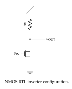
Solved An NMOS RTL INVERTER is configured as follows: Source | Chegg.com

CMOS Inverter - Siliconvlsi

What is CMOS Inverter? - Working, Applications [GATE Notes]

Draw a CMOS inverter :: Documentation in English

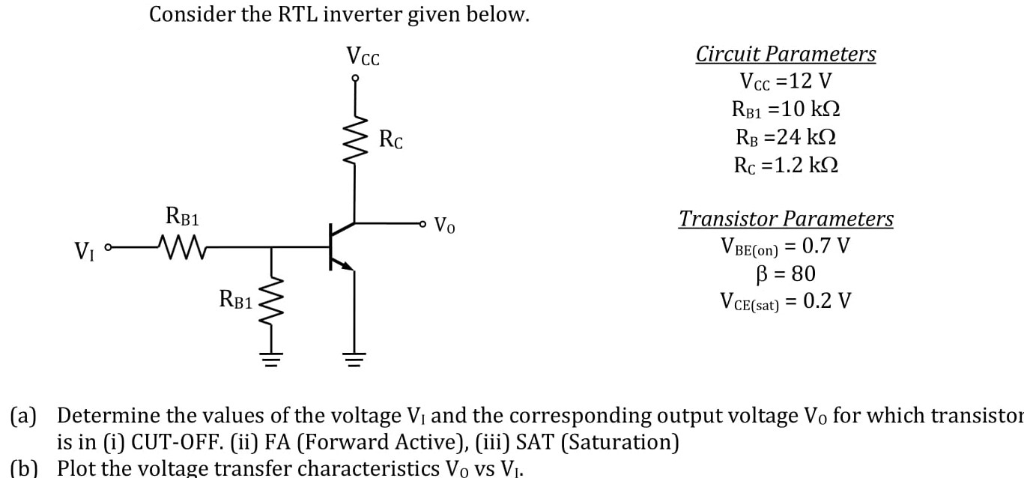
Solved Consider the RTL inverter given below. Circuit | Chegg.com

State of CMOS Inverter - Electrical Engineering Stack Exchange

Solved) - For the unloaded RTL inverter of Figure 5.83, V IN = 1.1 V as...  - (1 Answer) | Transtutors
Solved) - For the unloaded RTL inverter of Figure 5.83, V IN = 1.1 V as... - (1 Answer) | Transtutors

Virtual lab
Virtual lab

Why/What is load capacitance in CMOS inverter? - Quora

Illustrating the Circuit Idea of Conventional RTL inverter, Darlington... |  Download Scientific Diagram
Illustrating the Circuit Idea of Conventional RTL inverter, Darlington... | Download Scientific Diagram

File:CMOS inverter.svg - Wikipedia